Solar Wiring Diagrams for Home: Series, Parallel & Designing Your System
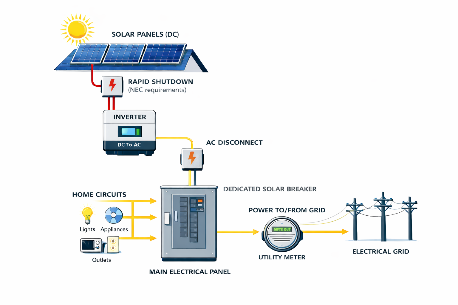
This graphic shows the basic flow of power through a home solar system, from roof to grid.
Designing or reviewing a solar wiring diagram doesn’t have to feel like studying an electrical blueprint. Whether you’re vetting an installer’s plan or sketching your own off‑grid setup, this guide walks you through the essentials: what a solar wiring diagram is, how series and parallel connections affect voltage and current, how to size your system and pick components, and why safety and code compliance matter.
What Is a Solar Wiring Diagram?
A solar wiring diagram is a graphic representation of how photovoltaic (PV) modules connect to other components—like charge controllers, batteries, inverters and disconnects—to form a complete energy system. It should clearly show where DC power is generated, where it is converted to AC, how it ties into your home’s electrical service and what happens if the grid goes down. Detailed diagrams are essential for planning and troubleshooting; wiring incorrectly can damage equipment or be life‑threatening.
Series vs. Parallel vs. Series‑Parallel Connections
Solar panels and batteries can be wired in series (positive to negative), parallel (positive to positive) or a series‑parallel hybrid. Understanding these orientations helps you choose the right configuration for your voltage and current needs.
Series Wiring
When panels (or batteries) are wired in series, the positive terminal of one connects to the negative of the next. This adds the voltages while the current stays the same. For example, four panels at 20 V and 5 A each produce 80 V and 5 A in series.
Pros:
Simpler cabling: Low current means smaller, inexpensive wires that are easier to manage.
Efficient long runs: Higher voltage reduces line losses and is often required for 24 V or 48 V battery banks.
Cons:
Requires MPPT charge controller: High voltage must be regulated with a maximum power point tracking (MPPT) controller, which costs more than a pulse‑width modulation (PWM) controller.
Shade sensitivity: Shading one module reduces the performance of all panels in a series string.
Parallel Wiring
In parallel wiring, all positive terminals are connected together and all negative terminals are connected together. This keeps the voltage constant but adds the currents. Four 20 V, 5 A panels in parallel deliver 20 V and 20 A.
Pros:
Lower controller cost: Because the voltage stays at panel level, you can use a less expensive PWM charge controller.
Shade tolerance: Each panel operates independently, so shading one panel has less impact on the others.
Cons:
Thicker cabling: Higher current requires larger, more expensive wires, and cable runs can become bulky and harder to hide.
Series‑Parallel (Hybrid) Wiring
Hybrid wiring combines series and parallel strings. Two or more panels are wired in series to boost voltage, and those series strings are then wired in parallel to boost current. Hybrid arrays balance voltage and current, making them common for larger residential systems where shading and cable runs vary.
| Orientation | Voltage effect | Current effect | Typical use-case |
|---|---|---|---|
| Series | Voltages add; current stays the same | Lower current allows smaller cables; requires an MPPT controller | 24 V or 48 V battery banks and long cable runs |
| Parallel | Voltage stays the same; currents add | Higher current means thicker cables; PWM controller acceptable | 12 V systems and shaded arrays |
| Series‑Parallel | Balances voltage and current | Combines series strings connected in parallel, providing moderate voltage and current | Larger arrays where shading and voltage requirements vary |
Component Guides for Your Solar Wiring Diagram
Designing a solar power system goes beyond connecting panels and batteries. Each component plays a specific role in generating, storing and distributing electricity. To help you explore the parts of a PV system in depth, we’ve created a series of companion guides. Use the links below to learn more about each component and how to size and install it properly.
| Component | Purpose |
|---|---|
| Solar panels | Convert sunlight into DC electricity. Learn about monocrystalline, polycrystalline and thin‑film panels and how to choose the right type for your roof. |
| Inverters | Convert DC from panels and batteries into usable AC power. Compare string inverters, microinverters and hybrid models. |
| Batteries | Store excess solar energy for use at night or during outages. Understand lithium‑ion, lithium iron phosphate and lead‑acid chemistries. |
| Charge controllers | Regulate the voltage and current from panels to charge batteries safely. Decide between MPPT and PWM technologies. |
| Cables & wires | Carry current between components. Learn how to size wire and minimize voltage drop. |
| Fuses & breakers | Protect circuits from overcurrent events. Compare fuses and DC breakers and learn where to use each. |
| Disconnect switches | Provide a safe way to isolate solar and battery circuits for maintenance or emergencies. |
| Inverter‑chargers | Combine inversion and battery charging functions to manage solar, battery and shore power seamlessly. |
| Battery isolators | Charge multiple batteries from one source without discharging the starter battery. |
| Battery monitors & shunts | Monitor current, voltage and state of charge to protect your batteries. |
| Busbars | Simplify wiring and distribute power efficiently across multiple connections. |
| Shore power | For offgrid systems: plug into external AC power sources at campgrounds or marinas to recharge batteries and run high‑demand appliances. |
| 12‑V switches & outlets | For offgrid systems: control and distribute low‑voltage DC power to lights, pumps and electronics. |
String Inverters vs. Microinverters and DC Optimizers
Most home solar systems use either string inverters or module‑level electronics such as microinverters or DC optimizers. A string inverter converts the combined DC output of a series or series‑parallel array into AC power. This configuration is cost‑effective but susceptible to shading—if one panel underperforms, the whole string’s output drops.
Microinverters, on the other hand, perform DC‑to‑AC conversion at each panel. This design improves shade tolerance and allows easier expansion, but costs more and introduces multiple points of failure. DC optimizers condition DC at each module before sending it to a central inverter; they offer a middle ground with improved monitoring and partial shade resilience.
Choosing between these options depends on roof layout, shading, budget and desired monitoring granularity. In our companion article on how solar panels work, we break down these technologies in more detail.
Designing Your Wiring Diagram: A Step‑by‑Step Checklist
Creating or reviewing a wiring diagram involves more than drawing lines; it’s about understanding your energy needs and ensuring all components work together safely. Here’s a roadmap:
Define your goals. Estimate your daily energy consumption in kilowatt‑hours (kWh) and decide whether you need backup power. If you haven’t already, read our guide on roof space for solar panels to size your array appropriately.
Choose your components. A basic system includes solar panels, a charge controller, a battery bank (optional for grid‑tied systems), an inverter and properly rated cables and fuses. Off‑grid or RV systems may also need a fuse box, DC disconnect, busbars, and monitoring devices.
Select wiring orientation. Use series connections for high‑voltage battery banks (24 V or 48 V), parallel connections for 12 V systems and shaded arrays, and hybrid configurations for larger homes. Consider the type of charge controller: MPPT controllers handle high voltage but cost more.
Calculate wire gauge. Wire size depends on current and distance. As a rule of thumb, 14‑gauge wire handles up to about 15 A, while higher‑current systems require 10–12 gauge wire or thicker. Consult a wire‑sizing calculator to minimize voltage drop.
Draw and label your diagram. Sketch the panels, controller, battery and inverter. Use red lines for positive and black for negative, and label each connection. Include fuses or breakers near the panels and batteries, rapid‑shutdown devices and a main DC disconnect.
Review for safety and compliance. Ensure your design meets National Electrical Code (NEC) requirements and local permitting rules. Solar work can involve dangerous voltages; if in doubt, hire a licensed electrician or solar installer.
System Sizing and Site Assessment
Before drawing any wires, assess your site and energy needs. Calculate how many kilowatt‑hours you use annually and decide how much of that you want solar to cover. Factors like roof orientation, shading, climate and available sunlight hours determine how much power your system will actually produce. The U.S. Department of Energy’s guide to planning a home solar electric system provides a detailed checklist for assessing solar potential, estimating electricity needs and obtaining bids.
Consult local building codes and HOA rules to determine permitting and inspection requirements. In many jurisdictions, grid‑tied systems with batteries require a licensed professional to install and commission them.
What Changes When You Add a Battery?
Adding battery storage transforms your system from a simple grid‑tie into a hybrid or off‑grid setup. In a grid‑tied system without a battery, the inverter shuts down when the utility grid goes down to protect line workers. With a battery and hybrid inverter, your wiring diagram will show additional components: the battery bank, a transfer switch or isolation device and a critical‑loads panel for backup circuits. Make sure your diagram labels which circuits will stay powered during an outage and how the system isolates from the grid.
Safety and Regulatory Considerations
Working with DC and AC electricity can be hazardous. Always include properly rated fuses or breakers, disconnects and rapid‑shutdown devices in your design. Use weather‑resistant, UL‑listed connectors and follow NEC guidelines for wire sizing and conduit. Because solar installations involve permits and inspections, most homeowners should partner with a licensed installer or electrician, especially for grid‑tied or battery systems. Diagrams are useful for understanding and verifying your system but are not a substitute for professional training.
Example Wiring Diagrams
Below are simplified diagrams for common configurations. These visuals are for educational purposes; always consult the manufacturer’s manuals and local code when wiring your system.
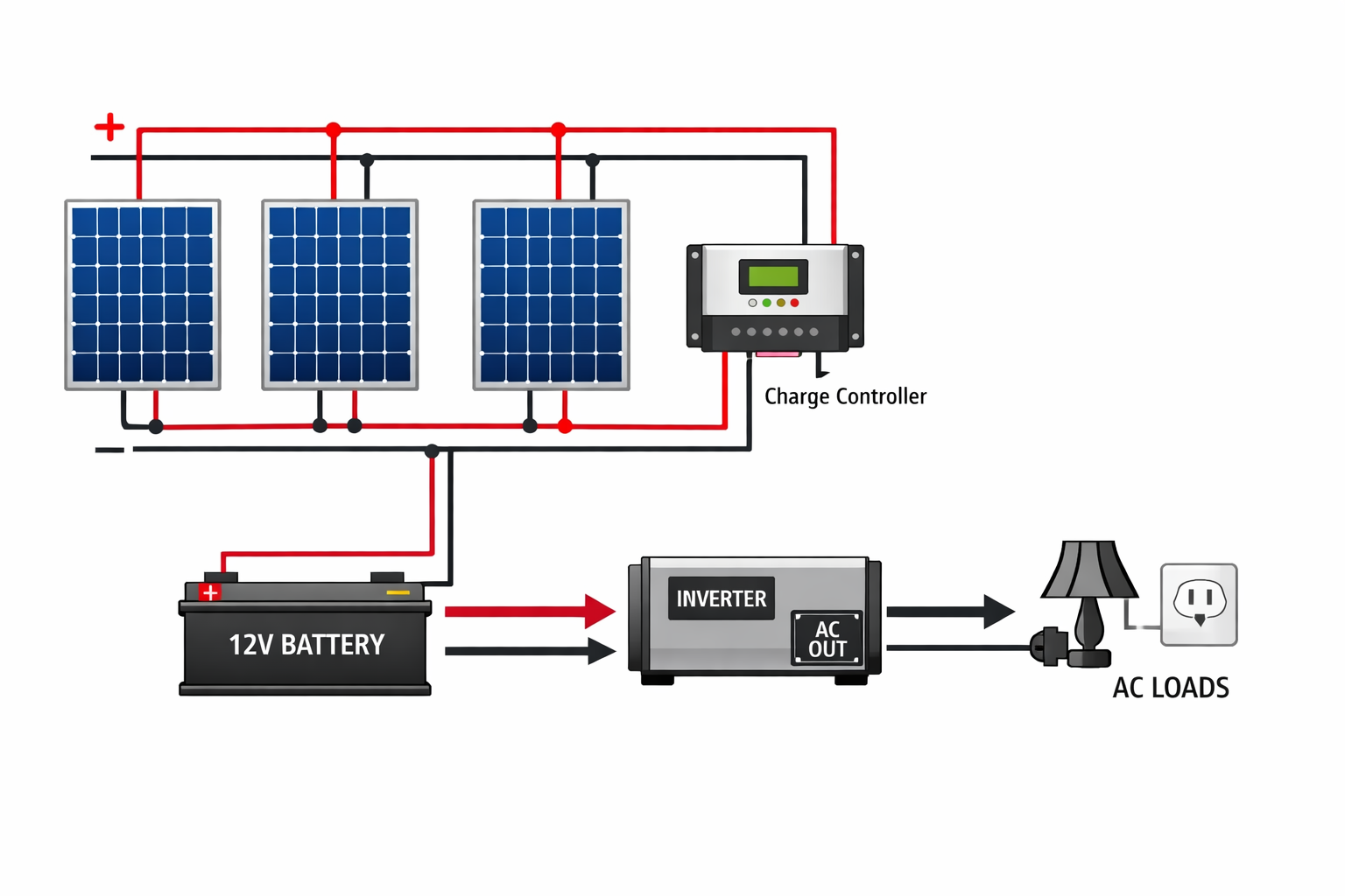
12 V System (Panels and Battery in Parallel)
In a 12 V system, panels and batteries are typically wired in parallel. This keeps voltage at 12 V while increasing current, allowing devices designed for 12 V to run longer. You’ll need a charge controller that matches your battery voltage and an inverter to convert DC to AC for household use.
Key points:
Panels wired positive‑to‑positive and negative‑to‑negative; voltage stays 12 V, current adds up.
Use a PWM or MPPT controller sized for your maximum current.
Wire from the battery to an inverter sized for your expected AC load.
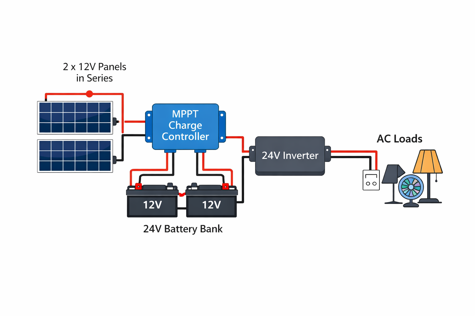
24 V System (Panels and Batteries in Series)
For 24 V systems, connect panels in series to double the voltage and keep current the same. Batteries are also wired in series. Higher voltage reduces cable size and is more efficient for longer runs and larger inverters.
Key points:
Two 12 V panels wired positive‑to‑negative output ~24 V; two 12 V batteries wired similarly yield a 24 V bank.
Requires an MPPT charge controller that can handle the higher voltage.
Use a 24 V inverter to convert DC to AC.
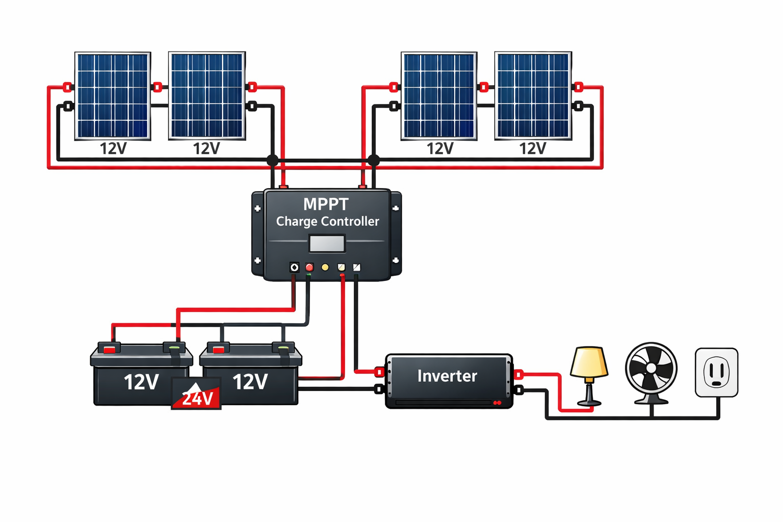
Hybrid Series‑Parallel Array
Larger arrays often combine series and parallel connections. The diagram below shows four panels arranged as two series strings that are then paralleled. This configuration balances voltage and current and offers better shade resilience.
Key points:
Each string has two panels wired in series; the two strings are wired in parallel.
Suitable for larger arrays where you need moderate voltage and current.
Use appropriately sized charge controllers and battery banks.
Frequently Asked Questions
How do I wire a solar panel system? Determine your battery voltage and choose series, parallel or hybrid wiring accordingly. Connect panels to a charge controller, then to a battery bank and inverter. Label positive and negative wires and include fuses and disconnects.
What wire gauge do I need? Wire size depends on current and run length. Fourteen‑gauge solar wire handles up to about 15 A, while higher currents require 10–12 gauge or thicker cable.
How does solar connect to my main panel? In grid‑tied systems, AC output from the inverter connects to your home’s breaker panel. A grid‑tie without storage shuts off during power outages to protect line workers. Hybrid systems use a transfer switch and critical‑loads panel to provide backup power.
Should I DIY my wiring? Wiring diagrams are valuable for understanding and verifying your system, but solar work involves permits and dangerous voltages. It’s wise to use diagrams for planning and hire a licensed professional for installation.
Final Thoughts and Next Steps
Solar wiring diagrams help you visualize how your system comes together. Understanding series and parallel connections, choosing the right components and sizing your system correctly ensure a safe and efficient installation. If you’re comparing installer proposals, use these guidelines to ask informed questions about power flow, shutdown points and backup circuits.
Ready to take the next step? Explore our articles on how solar panels work for your home and roof space for solar panels to deepen your understanding. You can also check the Department of Energy’s planning guide for detailed system design tips. When you’re ready for personalized advice or a custom wiring diagram, book a consultation with our team—we’re here to help you build a system that’s safe, efficient and ready for the future.